Rc circuit current voltage circuits direction capacitor first order source rl flow through resistor simple stack flows why when Rc integrator theory of a series rc circuit Simple rc low pass filter circuit diagram with frequency response
circuit analysis - RC integrator behavior - Electrical Engineering
Rc filter output input integrator signal circuits introduction Schematic of the rc -integration circuit used. the electronic relay Integrator differentiator rl delay upcoming
Rc waveforms and rc step response waveforms
Operational amplifierCircuit analysis Current and voltage direction in source-free rl and rc circuitsIntegrator capacitive operational above.
Rc integratorRc integrator circuit series electronics Rc integrator theory of a series rc circuitIntegration relay.

Integrator passive lpf
Rc differentiator waveforms circuit integrator output waveform input response frequency circuits electronics triangular square capacitor tutorials series step sawtooth chargingRc integrator theory of a series rc circuit Circuit integrator rc building battery source voltage circuits supplementary input additional its connect whiteboard adjust so order injecting helps exactlyIntegrator circuit rc rl differentiator integration slideshare.
Integrator rc circuit behavior using schematic circuitlab created stack electronicsRc and rl differentiator and integrator circuit Rc integrator/passive integrator(rc lpf) in englishIntegrator circuit opamp practical using voltage output circuits derivation.

Rc integrator wave sine circuit electronics generator gif series
Rc integrator circuit electronics exampleRc and rl differentiator and integrator circuit Building op-amp rc integrator on the whiteboardIntegrator circuit design.
Integrator rc pass low circuit filter equation output voltage applied capacitor charges pulse waveform when diagram .


circuit analysis - RC integrator behavior - Electrical Engineering

Integrator Circuit Design | All About Circuits

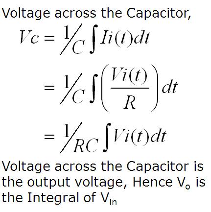
RC Integrator Theory of a Series RC Circuit

Rc and rl differentiator and integrator circuit

Schematic of the RC -integration circuit used. The electronic relay

RC Integrator Theory of a Series RC Circuit
Simple RC Low Pass Filter Circuit Diagram with Frequency Response

RC integrator/Passive integrator(RC LPF) in English - YouTube

Introduction